Furniture manufacturing 101
How flat-pack furniture is actually put together — the boards, the holes and the hardware. No workshop experience assumed. Every number here is one our own solver applies when it designs a cabinet.
Chapter 01
Boards and materials
Almost all flat-pack furniture is made from three boards — chipboard, MDF and plywood — in a handful of thicknesses. Which one goes where is not taste. It follows from three questions: how far must it span, how wet will it get, and does anything screw into its edge.
What we actually cut
Not every thickness exists. A 17 mm panel is not a board, it is a rounding error, and a design that asks for one is sent back — that is the thickness_in_catalog check. This is the whole stock list.
| Board | Core | Thickness | Sheet (mm) | Normally used for |
|---|---|---|---|---|
| MFC 8 | Particleboard, melamine-faced | 8 mm | 2800 × 2070 | Thin decor-matched panels |
| MFC 16 | Particleboard, melamine-faced | 16 mm | 2800 × 2070 | Lighter carcasses |
| MFC 18 | Particleboard, melamine-faced | 18 mm | incl. oversized | The default carcass board |
| MFC 25 | Particleboard, melamine-faced | 25 mm | 2800 × 2070 | Worktops, heavy shelves |
| MDF 3 | MDF | 3 mm | standard | Back panels |
| MDF 12 / 15 / 18 / 25 | MDF | 12–25 mm | incl. oversized | Doors and fronts; painted work |
| PLY 9 / 12 / 15 / 18 / 25 | Plywood | 9–25 mm | standard, grain-locked | Drawer boxes; long shelves |
| MFC 18 MR · MDF 18 MR | Moisture-resistant (P5 / MR-MDF) | 18 mm | incl. oversized | Kitchens and bathrooms |
Oversized boards (4100 and 5600 mm long) exist for long runs and are flagged as a special order rather than used silently.
Bending: why a shelf sags
Stiffness is the property that decides a shelf, and the boards differ by a factor of three. Deflection goes as span⁴ ÷ thickness³, which is the single most useful fact in this chapter: double the span and you get sixteen times the sag, while adding half again to the thickness only cuts it to about a third. Span is what to fix.
Stiffness (modulus of elasticity) — WoodHB Table 12-1
| Material | MOE (GPa) | What it means in practice |
|---|---|---|
| Solid hardwood | ~13 | 3–5× stiffer than any panel |
| Plywood | 7.0–8.6 | Stiffest panel per weight, least creep |
| OSB | 4.4–6.3 | Structural, rarely a furniture face |
| MDF | ~3.6 | Machines, paints and edges best |
| Particleboard | 2.8–4.1 | Cheapest and flattest — sags and creeps worst |
Maximum unsupported span, 18–19 mm shelf
| Material | Book load | Heavy load | Sources |
|---|---|---|---|
| Particleboard / melamine | ~600 mm | 450 mm | Rae · PanelGuide · web converge |
| MDF | ~700 mm | ~525 mm | Rae 711 · PanelGuide ~700 |
| Plywood | ~800 mm | ~600 mm | Rae 813 · PanelGuide ~800 |
| Solid hardwood | ~900–1000 mm | ~750 mm | Rae 1067 |
For 15 mm reduce about 15%; for 25 mm add about 30%. Sustained load needs a 2–3× creep margin — chipboard and MDF keep sagging for months after the books go on. Over the limit, stiffen rather than thicken: a back ledge, a front lip, or a divider that halves the span.
Moisture
Sheet goods are dimensionally stable — the grain-direction and wood-movement rules that govern solid timber simply do not apply, which is why a melamine carcass needs no expansion allowance. What they are not is waterproof.
For kitchens and bathrooms the answer is a moisture-resistant core: P3 or P5 particleboard, or MR-MDF (usually tinted green so it can be told apart on site). Resistant, not immune — no interior panel survives standing water, and the failure is irreversible swelling rather than a stain.
Screws, and the one rule that catches everyone
Particleboard holds a screw in its face and barely at all in its cut edge. The edge is loose chip ends; a screw driven into it pulls out under load. That single fact is why carcass corners use a cam and dowel instead of screws, and why the only screw you may drive into a board edge is a confirmat, which is designed for it.
Minimum edge distance for a face fixing — PanelGuide Table 4.7
| Board | Min. edge distance | Notes |
|---|---|---|
| MDF | 12 mm | Holds in face AND edge |
| Particleboard / OSB | 8 mm | Face only — its cut edge holds screws poorly |
| Plywood | 9 mm | Holds well in both |
| Any, at a corner | 25 mm (15 mm ply) | Whichever is greater: this, or 3× the fixing diameter |
Fixing length at least 50 mm or 2.5× the panel thickness; diameter about 0.16× thickness. Pilot holes are required in MDF and chipboard.
Which board goes where
| Part | Default | Why |
|---|---|---|
| Carcass sides, top, bottom | 18 mm melamine particleboard | Cheap, flat, good face screw-hold |
| Shelves | 18 mm MDF — plywood over 600 mm or heavy | Stiffest per weight, least creep |
| Doors and fronts | MDF | Paints, routs and veneers cleanly; never veneer-core, it warps |
| Back panel | 3 mm MDF, one side white | Non-structural: stops racking and dust |
| Drawer box | 12 mm plywood | Flat and void-free |
| Kitchen / bathroom | P5 particleboard or MR-MDF | No interior panel is waterproof — this is resistance, not immunity |
Chapter 02
Hinges
Almost every modern cabinet door hangs on a concealed hinge — the kind that disappears when the door is shut. It has three parts, and once you can name them the rest of the subject gets much easier.
How it works
The cup is a 35 mm round bore in the back of the door. The arm folds out of it. The mounting plate screws to the inside of the carcass side panel. The crank in the arm is what lets the door swing clear of the cabinet instead of jamming against its own edge.
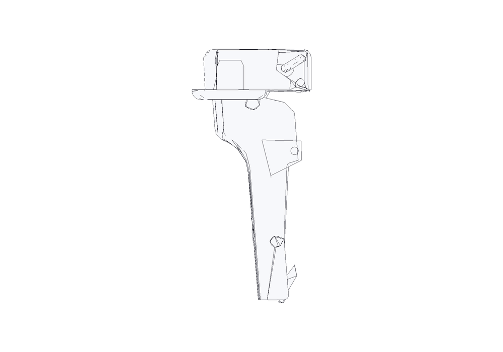
CLIP top BLUMOTION · manufacturer CAD, datum frame, viewer LOD · component 43224937
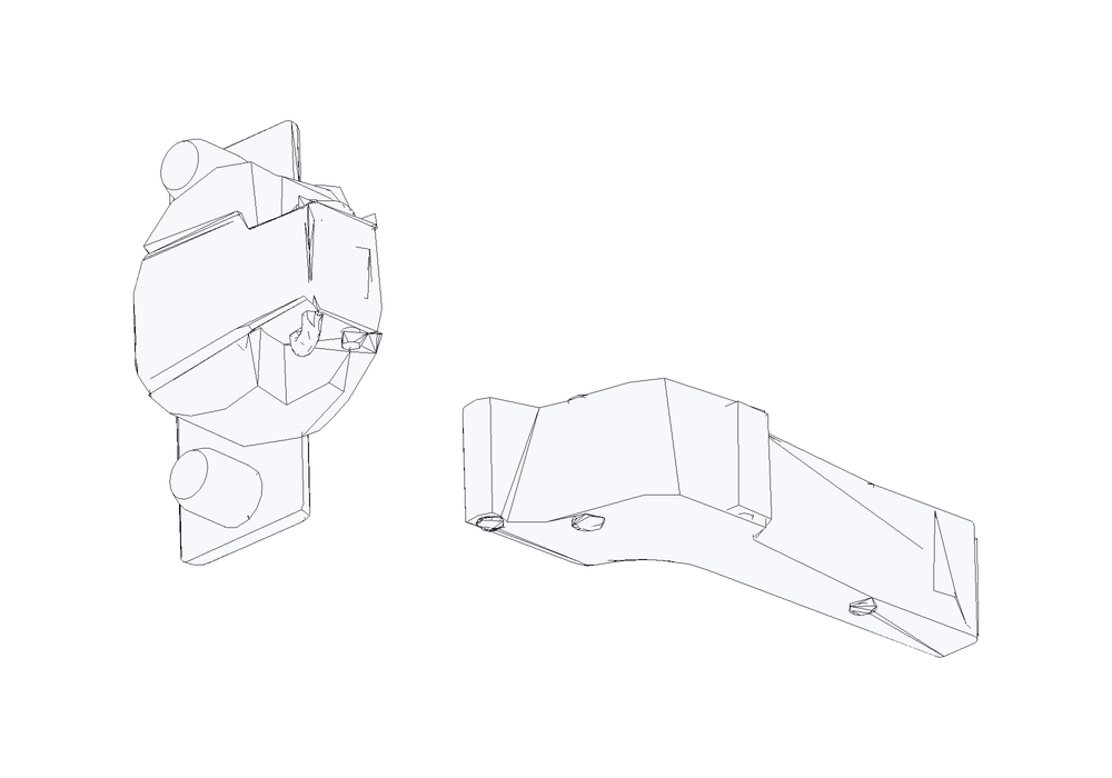
CLIP top BLUMOTION · manufacturer CAD, datum frame, viewer LOD · component 43224937
We do not animate the swing, and that is deliberate. A concealed hinge is a multi-bar linkage whose pivot travels as the door opens, and manufacturers publish reveal tables — angle against gap — rather than the linkage geometry. Any picture of this hinge half-open would be our guess at a shape, drawn at the same scale as the real parts and impossible to tell apart from them.
What the maker does publish is below.
Full overlay, half overlay, inset
A hinge is chosen for where the door sits relative to the carcass side, and that is the overlay. It is not an adjustment — it is a different hinge, with a different crank pressed into the arm. Buying the wrong one is the most common ordering mistake there is, because all three look nearly identical in a catalogue photograph.
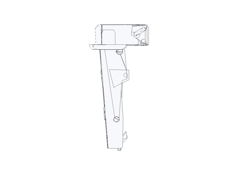
CLIP top BLUMOTION · manufacturer CAD, datum frame, viewer LOD · component 42592305
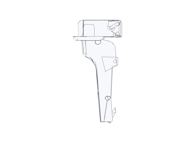
CLIP top BLUMOTION · manufacturer CAD, datum frame, viewer LOD · component 43224937
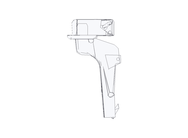
CLIP top BLUMOTION · manufacturer CAD, datum frame, viewer LOD · component 47572667
If those three look almost the same to you, that is the correct reading and it is the point. Measured off the CAD, the door halves are identical — 38.0 × 57.8 × 20.1 mm in all three. The entire overlay difference lives in the carcass half, which steps by about 9.5 mm each time:
| Overlay | Where the door sits | Used when | Arm depth | Component drawn |
|---|---|---|---|---|
| Full overlay | Covers the whole panel edge | One door per carcass side | 19.4 mm | 42592305 |
| Half overlay | Covers half the panel; its neighbour takes the other half | Two doors meeting on a shared panel | 28.9 mm | 43224937 |
| Inset | Sits flush INSIDE the opening, not over it | A flush, framed look; costs interior width | 37.4 mm | 47572667 |
Arm depths are measured from the manufacturer CAD, not quoted. Because the cup half is common to all three, the SAME door drilling serves every overlay — you change the hinge, not the door. Cup fixing is a separate axis again: press-in, screw-on or expando changes how the cup is held in the door, not where the door sits.
The numbers that matter
Chapter 03
Drawers and runners
The single most common beginner mistake is building the drawer box the same width as the hole it goes into. It never is — the runners need that space.
Seen from the side. Pull the slider to extend the drawer. The runner is in two parts: one screwed to the carcass, one to the box.
The three kinds of runner
Runners differ in where they sit, and everything else follows from that. A side-mount runner lives in the gap beside the box and you see it when the drawer is open. An undermount lives underneath and you never see it, which is why it costs more and demands a more accurate box.
| Type | Where it sits | Box width | Typical load | Extension | Character |
|---|---|---|---|---|---|
| Side-mount, ball bearing | On the side of the box, visible when open | Opening − 25.4 mm (½″ each side) | ~45 kg | Full or partial | Cheapest, most forgiving of a rough opening. The runner is on show. |
| Undermount | Beneath the box, hidden | Opening − 42 mm (Blum MOVENTO) | 40–70 kg | Full, with soft close | Invisible in use, so the box sides read as furniture. Needs a precise box and a recess in its base. |
| Roller (single extension) | On the side, epoxy-coated | Opening − 25.4 mm | ~25 kg | Partial only | The cheapest option and it shows: the back of the drawer never clears the carcass. |
There is no price column, deliberately. Our fittings catalogue holds no price data for any article, so any cost ranking here would be invented. Where price matters to a choice, the honest answer is that we cannot rank on it — the same reason the connector selector ranks on capability and abstains on cost.
Picking a load class
Pick by what goes in, not by what is cheapest. A cutlery drawer and a pan drawer are not the same problem, and the class is a published figure rather than a judgement — a file or pantry drawer also needs full extension, because the back half is unreachable otherwise.
Published load classes
| System | Class |
|---|---|
| Blum METABOX | 25 kg |
| Blum TANDEM / TANDEMBOX antaro | 30 kg |
| Blum LEGRABOX 750 · MERIVOBOX 450 · MOVENTO 760H | 40 kg |
| Generic ball-bearing side-mount | ~45 kg |
| Blum MOVENTO 769 (heavy undermount) | 56–77 kg |
| Blum TANDEMBOX 576 | 65 kg |
| Blum LEGRABOX 753 · MERIVOBOX 453 · MOVENTO 766H | 70 kg |
Mounting flat or vertically derates a runner by roughly 30%. Sources: Blum, AWS, trade data via the manufacturing knowledge base §2.6.
Why the box is narrower than the hole
Seen from the front. The runners live in the gap either side — build the box to the opening width and it will not go in.
Chapter 04
Connectors and joints
A flat-pack carcass is held together by fittings, not by glue and skill. The choice is narrower than it looks: how the panels meet, whether it must come apart again, and — the one that decides it in practice — what the workshop can machine.
| Joint | Typical article | Machining | Comes apart? | Visible? | Character |
|---|---|---|---|---|---|
| Cam and dowel | Hettich Rastex 15 · Häfele Minifix | Ø15 cam in the face, 34 mm from the edge; Ø8 dowel on the mating edge | Yes | Yes — cam head shows inside | The default carcass corner. The cam both aligns AND clamps, closing a gap up to 4 mm. |
| One-piece surface connector | Lamello Cabineo 12 | A milled pocket on each panel face — no edge drilling at all | Yes | Cap on one face | Both operations are on the broad face, so a 3-axis nester builds a carcass without ever turning a panel on edge. Needs a router, not just a drill. |
| Confirmat screw | Ø5 / 6.3 / 7, stepped pilot | Straight into the board edge | No — one-way in practice | Head shows unless capped | The ONLY screw that may be driven into a particleboard edge. Coarse deep thread cut for chip. |
| Dowel | Beech, Ø8 × 30–40 mm | Ø8 in both parts, 150–200 mm centres | No — glued | Invisible | Alignment and shear. Never used alone on a knock-down joint: it cannot pull a joint together. |
No price column, again deliberately — the catalogue holds no price data. And for connectors price is rarely the binding constraint anyway: Cabineo needs a Ø12 pocketing cutter, so a shop whose smallest cutter is 16 mm cannot make that joint at any price. Machinability rules the choice in or out before cost ever ranks it.
The pairing rule
A cam and a dowel are not alternatives — they do different jobs and are used together. The cam takes tension, pulling the joint closed and holding it there; the dowel takes shear and does the alignment. A cam alone lets the panel slide; a dowel alone cannot pull anything together.